LATEST UPDATES

Monday, 23 March 2020

SHAFT ALIGNMENT

SHAFT ALIGNMENT, Shaft Alignment - Fundamentals, HOW TO DO SHAFT ALIGNMENT,
Shaft Alignment - Fundamentals
          Shaft alignment is process of positioning (or) aligning of shaft center lines of the driven and driver components (i.e., gearboxes, pumps, rolls etc.,) within a tolerated margin. Alignment is accomplished by giving shimming or moving machine components or sometimes both. The aim of shaft alignment is to maintain a common axis of rotation at operating equilibrium for two coupled shafts.
          In case of high speed equipment if the shaft alignment is not perfect we cant get maximum reliability and life through that equipment. Alignment is important in the case of direct coupled shafts and also the shafts of machines that are separated by distance even though we use flexible coupling. Shaft alignment is very important why because due to misalignment a lot of stress on shafts, vibration and noise produces. This causes excessive wear, bearing problems like heating and bearing failure, and results in the need for frequent repairs. By proper alignment we can reduce noise, vibration and also power consumption and this helps to achieve the design life of bearing, seal, shaft and coupling. 
          Alignment procedure is done by assuming a machine component is stationary, level and supported properly its base plate and foundation. Both angular and offset alignment must be performed in the vertical and horizontal planes, which is obtained by moving horizontally or by raising or lowering to align with the rotational center line of the stationary shaft. The movable components are designed as Machines To Be Moved (MTBM) or Machines To Be Shimmed (MTBS). MTBM generally refers to correction in horizontal planes and MTBS refers to corrections in vertical planes. 


Sunday, 22 March 2020

Ribbon Blender: Construction, Operation, and Applications

          RIBBON BLENDER (or) mixer machine is widely used for dry powder, Grannules, Low-viscosity paste and liquid in chemicals, food and cosmetics industries. It is particularly appropriate for combining solids and solids with liquids, Approximately two third of the volume of the container of ribbon blender is stuffed to make sure proper mixing.
           The Ribbon Blender can be used in either batch or continuous flow form to achieve even and homogeneous blending.

Construction & Operation:
          Ribbon blender consists of a "U"-shaped trough containing a double helical ribbon mixer that rotates inside. The blender's shaft is positioned within the centre of the through and has welded spokes on that helical ribbons (also referred as spirals) are welded. Since the agitator consists of a group of inner and outer helical ribbons, it is said as a "double" helical ribbon agitator. The gap between the ribbon's outer edge and the internal walls of the vessel ranges from 4 to 5 mm depending upon application.
Ribbon Blender, Ribbon Blender internal view
Ribbon Blender

          Generally the ribbon blender is powered by a drive system consists of motor, coupling, and gearbox. For blending 500-1000 kg of product a 10 HP to 15 HP  motor is used.
          The agitator shaft exits the blender container at either end through the end plates secured or welded to the container. The area where the shaft exists the container is given a sealing arrangement to make sure that material doesn't travel from the container to the outside and vice-versa.
          The charging of material is generally done through top cover, the cover also contains cleaning and maintenance access. The material is to be blended are loaded into the blender upto 40 to 70 % of the total volume of container. This is generally up to the level of the outer ribbon;s tip. Depending upon the application the agitator is designed to operate at peripheral speed (also called as tip speed) approx 100 mtr/min.
          During blending, the outer ribbons move the material from the ends to the centre while the inner ribbons move the material from centre to ends. Radial movement is achieved because of the rotational motion of the ribbons. The difference in the pheripheral speeds of the outer and inner ribbons results in axial movement of the material along the axis of the blender. As a result of combining motions of these homogeneous blending is achieved in short time. The efficiency of the blender depends on particle size, density and quantity.
          After blending, the material is discharged form discharge valve located at the bottom of the through. The discharge can be fitted with any kind of valve like slider gate, butter fly depending upon the material. The operation of valve can be done by manual or automatic.
          The motion of the ribbons near the walls can result in "pinch" points, or regions of higher shear and compression, which may damage fragile material. In some cases this can leads to friction and heat generation resulting in product degradation.
          An alternate design to the ribbon blender is paddle agitator, which can handle fragile material. The paddle agitator is composed of both forward and reverse paddles in place of the ribbons. The paddles are positioned to  move the material in opposing lateral direction as well as in a radial direction. The ribbon design is appropriate for low and medium duty applications, hile paddle design is suitable for heavy duty applications. In some cases we can see hybrid-design like paddle and ribbon agitator.

Name plate details:


RIBBON BLENDER
ModelAFA-80300
Blending Capasity1 m3 (300 kg) or 1.8 m3 (500) kg
Motor Capasity7.5 KW (10 HP) or 11 KW
Speed rates20 RPM
Weight1.5 Ton or 2 Ton
MakeEx:Alpha Factory Automation Ltd
Ribbon Blender,
Ribbon Blender

Applications:
1) Blending large amount of dry solids.
2) Dry blending of capsule formulation.
3) Cooling, drying, heating of materials.
4) Blending of chemicals.

Materials commonly blended are:
Abressives
Plastic resigns
Epoxy resigns
Pharmaceuticals
Face powders
Fertilizers
Chemicals
Gypsum
Instant drink blends
Talcum powders
Laundry detergents


SHAFT ALIGNMENT -- FUNDAMENTALS

          In this article we are going to discuss the basic fundamentals of machine alignment. This section addresses precisely what alignment is and also what are the tools required to perform it, why it is required, how often it should be done and what steps should be taken prior to performing the alignment process.
          When the main shafts are collinear at the coupling point they are considered to be in alignment. Here the term collinear refers to the condition when the two rotating mating shaft's centerlines are parallel and intersect (i.e., join to form as a single line). When this is often the case the coupled shafts operate just like a solid shaft. Any slight deviation from the aligned or collinear condition. However, ends-up in abnormal sound, vibration and wear of machine elements such as bearing and shaft seals.
          Variations in machine-component configuration and thermal growth will cause mounting-foot elevations and the horizontal orientation of individual drive-train components to be in different planes. However, they are considered to be properly aligned as long as their shafts are colinear at the coupling point.

Tools we use:
          Generally we use Dial gauge, Taper gauges, Feeler gauges and Outside micrometer calipers in the alignment procedure.
SHAFT ALIGNMENT -- FUNDAMENTALS, SHAFT ALIGNMENT, shaft alignment equipment,
Equipment - shaft-alignment-options

WHY WE HAVE TO PERFORM ALIGNMENT AND HOW OFTEN?
          Vibration effects of misalignment can seriously damage a piece of equipment. Slight misalignment is also cause vibration, this vibration reduces equipment life. Periodically checking of all coupled equipment alignment is one of the best 'tool' in Preventive Maintenance.
          Although during installation and also in previous check the machine is properly aligned, misalignment may develop in short interval of time. There are many causes for misalignment they are thermal expansion, distortion of attached equipment, foundation movement or settling etc.,

By the below indications we can sense the misalignment of machine:
1) More vibration in both vertical and axial directions
2) Shaft wobling
3) Bearing temperature
4) Noise (From coupling and from bearing housing)
5) Coupling wear (In Lovejoy RNS coupling rubbers damage, In tyre coupling - coupling tyre wear).

ACTIONS TO BE TAKEN BEFORE ALIGNMENT:
          The alignment procedure is crucial so we have to be performed correctly. Using correct sequence is one of the most important factor in shaft alignment process. Understanding and using the correct actions will decrease the shaft alignment time and improve efficiency. In this article we are suggesting some actions to be taken before alignment, which cover the preparatory steps as well as two major issues (i.e., Soft-foot and Indicator sag corrections) that must be resolved before alignment can be accomplished. This section provides policies for making the right path to capture these corrections as well as the correct way to tighten hold-down nuts, an important process that is needed when the correcting soft-foot.
Image credits : Youtube --The Real Female Entrepreneur

Preparatory Steps :
          The following preparation actions should be taken before attempting to align a machine train:

1) The base of machine and the base where we kept machine is to be cleaned with a wire brush or a file, to make sure it is clean, burr free and rust free.
2) Prior to adjusting the driver unit align with drive unit, driven unit is to be placed to the required level, position, and secure. Keep the shaft centre line of the driven unit slightly more than the driver.
3) Make sure that the shims that we are using do not have any burrs and not been "kinked".
4) Make sure the shaft doesn't have an indicated runout.
5) Before starting the alignment procedure check for "soft-foot", and correct it.
6) Always tight the hold-down nuts in the correct tightening sequence.
7) Determine the amount of indicator sag before starting the alignment policy.
8) To avoid the lifting of the machinery more than that we need, add or remove shims.
9) Jacking bolt assemblies should be welded onto the bases of all large machinery. If they are not provided, add them before starting the alignment procedure. Use jacking bolts to adjust for horizontal offset and angular misalignment and to hold the machine in place while shimming.

Saturday, 21 March 2020

PROBLEM 1.2

Find the minimum diameter of a steel wire, which is used to raise a load of 6000 N, if the stress in the rod is not to exceed 105 MN/m2 .

Sol:

As per given data:
            Load           P = 6000 N
            Stress        σ = 105 MN/m2    = 105 x 10 6 N/m2            (1 MN = 106 N)
                                  = 105 N/mm2                                        ( 106 N/m2 = 1 N/mm2)
 Let       D = The diameter of the rod in mm
Area      A = (π/4) D2
We know that, Stress  σ = Load/Area = P/A
                                    105 = 6000/(π/4) D2
                                     D2 = 6000 x 4 / π x 105
                                     D   = 72.75

Friday, 20 March 2020

SCREW CONVEYOR

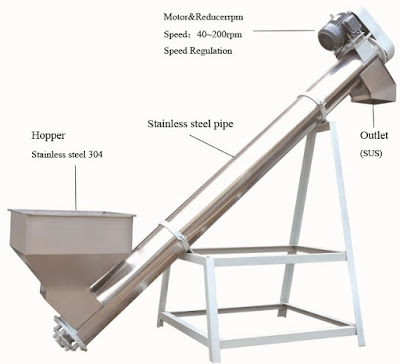
          A Screw conveyor or Auger conveyor is a mechanism that uses a rotating helical screw, usually within a tube (Trough), to move liquid or grannular materials. The rotating part of this type of conveyor is called Auger.
SCREW CONVEYOR -- PARTS

          Screw conveyor in modern industry are often used horizontally or at a slight inclined as an efficient way to move semi-solid materials, including food waste, boiler ash, powder materials, agricultural material and many other. The first type of screw conveyor was the Archimede's screw, used since ancient times to pump irrigation water.

          They usually consist a trough or tube containing either a spiral blade coiled around a shaft, driven at one end and held at the other end, or a "Shaftless spiral", driven at one end and free at other end. The rotational rate of shaft is directly proportional to the rate of material transfer.

          Screw conveyors can be operated with the flow of material inclined upward. As the angle of inclination increases, the capacity of a given unit rapidly decreases.

Types of screw conveyors:

1) Horizontal screw conveyor
2) Inclined screw conveyor
3) Shaft less screw conveyor
4) Vertical screw conveyor


Horizontal screw conveyor

Inclined Screw Conveyor

Shaftless Screw Conveyor

Screw Conveyor
Screw Conveyor


Source take from Wikipedia


@2020 All Rights Reserved. Designed by WWW.SMARTWAYTOSTUDY.COM !!!! Sitemap !!!! Blogger Templates