LATEST UPDATES

Sunday, 14 June 2020

AIR KNOCKER

          Air knocker is a kind of process automation equipment, designed to eliminate problems occurring due to the deposition of powder inside a hopper. This equipment consists of a "Magnetic Piston". Due to the interaction between Magnetic Piston and Air pressure this equipment dislodges some force on hopper. 
AIR KNOCKER

AIR KNOCKER
AIR KNOCKER


AIR KNOCKER NAME PLATE DETAILS


Saturday, 13 June 2020

TYPES OF FLANGES

Flanges can be classified in different ways as follows:


1. Based on Type of Connection:


a) Threaded Flanges:

         These types of flanges also called as "Screwed flanges", because these flanges having a thread inside the flange bore. The thread inside the flange bore which fits on the pipe which is having a matching male thread on the pipe. The main advantage of this flanges is that they can be attached to the pipe without any welding. In some cases a seal weld is also used in combination with a threaded connection. This type of joint connection and dismantling is speedy and also simple but for high pressure and temperature applications these are not suitable. It is also not suitable for a pipe system with thin wall thickness because thread cutting on a pipe of thin wall thickness is not possible so we have to choose pipe with thicker wall thickness.

TYPES OF FLANGES, THREADED FLANGES


b) Socket-weld Flanges:

          Socket-Weld Flanges features a female socket in which pipe is fitted. Generally Socket-weld flanges are used for small size (NPS 2 and smaller) and high pressure piping systems. These flanges static strength is equal to slip on flanges.

          The connection is done by inserting pipe into the recess area and 1 fillet weld is done from outside on the pipe. Before creating the welding, we need to create some space between the flange and pipe.

          To reduce the residual stress at the root of the weld that could occur during solidification of weld metal bottom clearance is given in the socket weld. In the bottom image X measures the expansion gap. 

Disadvantages: 

1. Maintain specific gap.

2. Cracking problems between the flange and pipe by corrosive  products can cause problems.

TYPES OF FLANGES, SOCKET WELD FLANGES


c) Slip on Flanges:


SPILLWAY

SPILLWAY, LEVEE, TYPES OF SPILLWAYS
          A spillway is a hydraulic structure built at a dam site for the controlled release of the surplus (or) excess water from Reservoir (or) Levee into a downstream area after it has been filled to its maximum capacity. In the United Kingdom, these are called as "Overflow Channels". Spillways ensure that the water doesn't overflow and damage (or) destroy the dam.

          Every reservoir encompasses a certain capacity to store water. If the reservoir is full and flood water enters it, the reservoir level will go up and may eventually result in over-topping of the dam. To prevent this situation, the flood has to be passed on to the downstream and this is done by providing a spillway which draws water from the top of the reservoir. A spillway are often a part of the dam or separate from it.

          Spillways can be controlled (or) uncontrolled. A controlled spillway is furnished (provided) with gates which can be raised (or) lowered. Controlled spillways have certain advantages. When a reservoir is full, its water level will be equal to the crest level of the spillway.

          If flood enters the reservoir at that point, the water level will start going up and simultaneously water will start flowing out through the spillway. After flood stops, the reservoir level will come down and eventually come back to the normal reservoir level.
          Spillways are classified into different types on the basis of the arrangement of the control structure, a conveyance channel and a terminal structure. Within the next article, we will discuss in brief all the different types of spillways with pictures.


Credits: QUORA

Friday, 12 June 2020

Fan Pump or Split-Case Pumps | | Use of Fan Pump in Paper Making Plant | |

What is a horizontal split case pump?
          "Horizontal split case pump is a type of centrifugal pump, within which the casing is divided into two separate chambers". It is completely different from an End suction pump (or) Inline pump. Within the End suction pump casing, the suction nozzle, and also the discharge nozzle are all enclosed in a single chamber.
FAN PUMP, SPLIT CASING PUMP
Image Courtesy: Https://www.pattersonpumps.com
          Based on design the split casing pumps are divided into two major types. When the casing is split along a vertical plane, in regard (reference) to the impeller, it is stated as a vertical split case pump; When it is split on horizontal plane, it is stated as horizontal split case pump. This kind of casing style is a lot of economical for higher flow applications, and also the impeller can be supported by bearings on both sides, an advantage for large, high flow pumps.
          The pump has the suction and discharge connections in the lower half of the casing, opposite to one another. The impeller is mounted on a shaft which is supported by bearings on each side.
          Split casing pumps are more costly than End-suction or Inline pumps and also not flexible and not adaptable as vertical turbines. However they are most durable, efficiency and dependability.
          A properly designed, installed, and operated split case pump can provide decades of life.

Axially- split horizontally- mounted pump Advantages:
Fan pump, Split case pump, Fan pump parts
          The most common split case pump is axially split (-- meaning the flange at which the pump casing separates in the same plane as the pump axis), a single- stage, between bearing, non-self priming centrifugal volute pump. The design of the pump allows for easy removal of the pump's top casing to enable easy and quick access to the pump's components without interfering with the motor or the piping system.
          Radially split casing pumps are also available in market; they are useful in very high pressure and high temperature industrial applications (Boiler- feed pumps are a common use for radially-split pumps).
          In some sort of designs, the independent bearing casing permits for easy maintenance without the requirement for removing pump's top casing. The pump's double volute design minimizes the radial load on the shaft, increasing parts life and reducing vibrations to provide quite operation.
          The split case pump is available on the market in numerous designs and also made from diverse materials to suit a wide range of applications. The main parts in the pump such as, impeller, casing, wear rings and shaft can be available in various materials to suite the fluid that is being pumped and the environmental conditions.
          The pump also comes in a variety of configurations and designs including horizontal, vertical open shaft and close coupled configurations; with counter clockwise or clockwise rotation design options.

Balanced Design:

Between-the-bearings: These pumps are also called as "Between-the-bearing" pumps. Because the impeller on the shaft is supported by bearings on both sides.

Double- suction impeller: A double suction impeller imposes fewer loads on the bearings when compared to the impeller that only draws in water from one side of the impeller (single-suction type).

Applications:

         Split case pumps are by design, a more balanced machine than the most other types of pumps. The versatile design of the split case pump, robust bearings and a maintenance friendly casing design makes it suitable for a wide range of domestic, municipal water, industrial (Paper, oil & gas plants) and other commercial applications. Multi-stage split case pumps provide economical, reliable high-head pumping for uses like booster service and boiler feed. Other applications include irrigation, public water supply, process cooling, public waterworks cooling systems, and HVAC.
FAN PUMP, SPLIT CASING PUMP

Use of FAN PUMP in Paper Plants:
          The finished slurry is diluted in silo with white water. The fan pump propels this diluted slurry for paper making towards the headbox. These pumps have been designed to reduce the pulsation, since the pump goal is to maintain constant weight overtime and avoid "Baring". At the inlet of the fan pump, thick stock, generally 3 to 5% consistency is diluted with white water. At the delivery end of the fan pump, the consistency of thin-stock around 0.3 to 1% solids. Mixing action of chemicals like fillers, acids and bases by paper makers before the fan pump happen within the fan pump.

Wednesday, 22 April 2020

STEAM TRAPS & TYPES OF STEAM TRAPS

          Steam-supply systems are commonly utilized in industrial facilities as a general heat source and also as a heat source in pipe and vessel tracing lines used to prevent freeze-up in non-flowing conditions. Inherent with the use of steam is the problem of condensation and the accumulation of non-condensable gasses in the system.

          Steam traps must be utilized in these systems to automatically purge condensate and non-condensible gasses, like air, from the steam system. A steam trap holds back steam & discharges condensate under varying pressure or loads. However, a steam trap should never discharge live steam. Such discharges are dangerous as well as costly.

The three important functions of steam traps are:
1) Discharge condensate as soon as it is formed (unless it is desirable to use the sensible heat of the liquid condensate).
2) Have a negligible steam consumption (i.e., being energy efficient).
3) Have the capability of discharging air and other non-condensable gasses.

Types of steam traps: Based on working principle

In industrial applications 5 major types of steam traps are used, they are: 
                    1) Inverted Bucket type
                   2) Float & Thermostatic
                   3) Thermodynamic
                   4) Bimetallic and
                   5) Themostatic
     Each of these steam trap use a different method to determine when and how to purge the steam system. As a result each has a different configuration.

Mechanical Steam Traps:

          Mechanical steam traps depends on the difference in density between steam and condensate in order to operate. They are able to continuously pass large volumes of condensate and are suitable for a wide range of process applications. Ball float and inverted bucket steam traps are some of the types of mechanical steam traps. This tutorial considers the operation and benefits of both types.

Inverted Bucket steam traps:
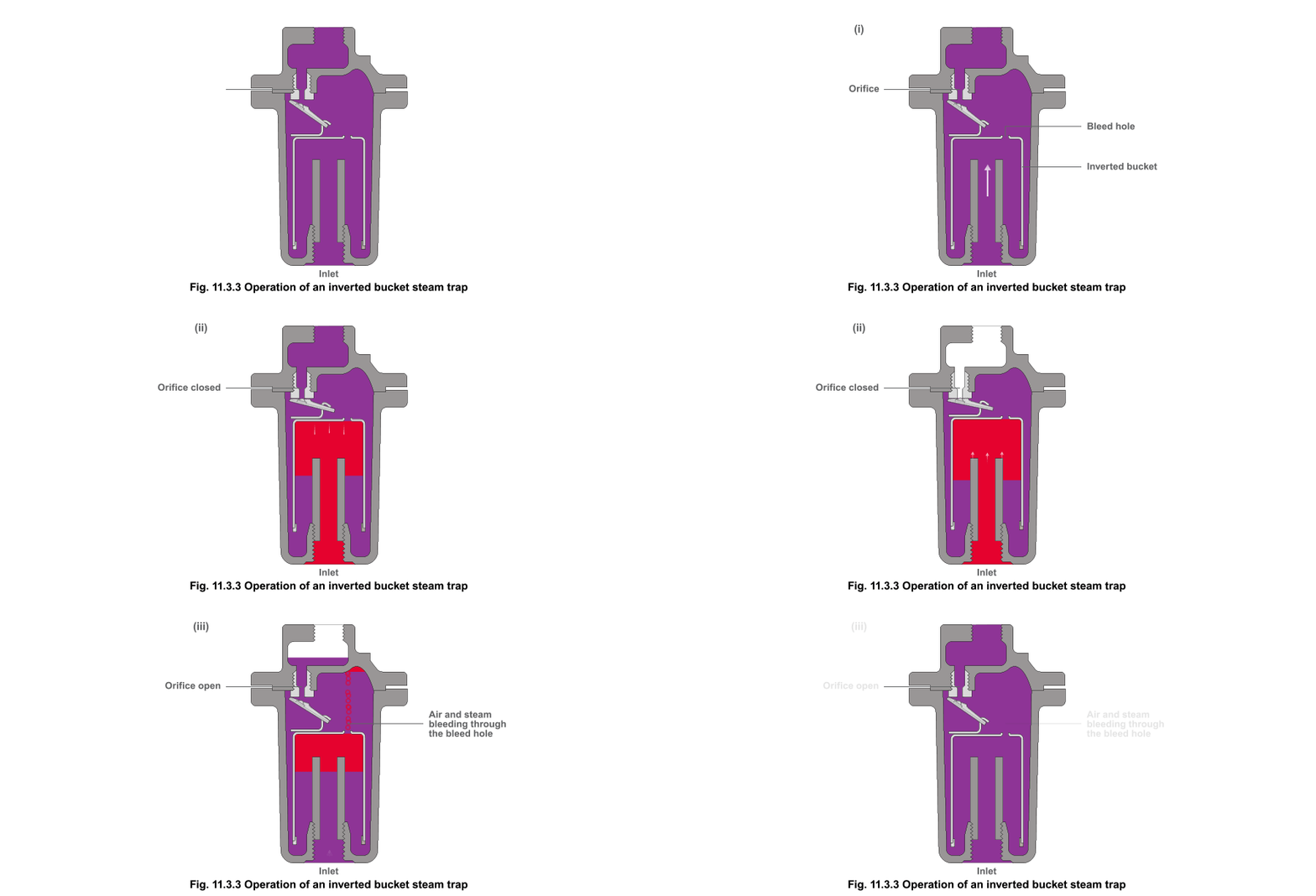
          The inverted-bucket trap, which is shown in fig., is a mechanically actuated steam trap that uses an upside down (or) inverted bucket as Float. This bucket is connected to the outlet valve through a mechanical linkage (called lever). 
          Below fig., shows the method of usage. In (i) first the bucket hangs down, pulling the valve off its seat. The condensate enters from bottom of the bucket filling the body and flows away from the outlet. In (ii) when the steam enters it causes the bucket to become buoyant, it then rises and shuts the outlet. In (iii) The trap (valve) remains shut until the steam in the bucket has condensed (or) bubbled through the vent hole to the top of the trap body. it will then sink, pulling the main valve off its seat. Accumulated condensate is released and the cycle is repeated.
Inverted bucket steam trap, Inverted bucket steam trap working
          Inverted-bucket traps can handle a wide range of steam pressures and condensate capacities. They are economical solution for low-to medium- pressure and medium-capacity applications. For high pressure and capacity applications, these traps become large, expensive, and difficult to handle.
          Each specific steam trap has a finite, relatively narrow range that it can handle effectively. For example, an inverted-bucket trap designed for up to 15-psi service will fail to operate at pressures above that value. An inverted-bucket trap designed for 125-psi service will operate at lower pressure, but its capacity is so diminished that it may back up the system with unvented condensate. Therefore it is critical to select a steam trap designed to handle the applications pressure, capacity and size requirements.

Float-and-Thermostatic:

          The float-and-thermostatic trap shown in fig., is hybrid type. The float similar that found in a toilet tank operates the valve. These traps operates by sensing the difference in density between steam and condensate. As condensate collects in the trap, it lifts the float and opens the purge (or) discharge valve. This design opens the discharge only as much as necessary. Once the built-in thermostatic element purges non-condensable gases, it closes tightly when steam enters the trap. The advantage of this type of trap is that it drains condensate continuously.
Float-and-thermostatic trap

          The key advantage of float-and-thermostatic trap is their ability for quick steam-system startup because they continuously purge the system of condensate, air and other non-condensable gases. One disadvantage is the sensitivity of the float ball to damage by hydraulic hammer.
          Float-and-thermostatic traps provide an economical solution for lighter condensate loads and lower pressures systems. However, when the pressure and capacity requirements increase, the physical size of the unit increases and its cost rises. It also becomes more difficult to handle.

Thermodynamic (or) Disk type:

          Thermodynamic, (or) Disk-type, steam traps use a flat disk that moves between the cap and the seat (See Figure). Initially, condensate flow raises the disk and opens the discharge port. Steam or very hot condensate that enters the trap applies pressure on the disc and seats the disk. It remains seated, closing the discharge port, until there is pressure is maintained above it. Heat radiates out through the cap, thereby diminishing the pressure on the disk, opening the trap to discharge condensate.
STEAM TRAPS , Thermodynamic steam traps, Disc type steam traps

          Wear and dirt are particular problems that we face with a disk-type trap. Due to the large, flat seating surface, any particulate contamination such as dirt or sand, lies between the disk and the valve seat. This prevents the valve from sealing and allows live steam to flow through the discharge port. If pressure is not maintained above the disk, the trap will operate frequently. This wastes steam and may cause the device to fail prematurely.
          The key advantage of these traps is that one trap can handle an entire range of pressures. In addition, they are relatively compact for the amount of condensate they discharge. In these type of traps disk is the only moving part, maintenance can easily be carried out without removing the trap from the line.
          The main disadvantage is difficulty in handling air and other non-condensable gases. Thermodynamic steam traps will not work positively on very low pressures.

Bi-metallic type steam traps:

          Bi-metallic steam trap works on the same principle as a residential-heating thermostat. As the name indicates, these traps are constructed using two strips of dissimilar metals welded together into one element. The element deflects when heated. A bi-metallic strip, or wafer, connected to a valve disk, bends or distorts when subjected to a change in temperature. When properly calibrated, the disk closes tightly against a seat when steam is present and opens when condensate, air, and other gases are present.
Bi-metallic steam traps, STEAM TRAPS

          The key advantages of bi-metallic traps are (1) Compact size compared to load-handling capabilities and (2) Immunity to hydraulic-hammer damage.
          Their biggest disadvantage is the need for constant adjustment (or) Calibration, which is usually done at the factory for the intended steam operating pressure. If the trap is used at a lower pressure, it may discharge live steam. If the trap is used at a higher pressure, condensate may back up into the steam system.

@2020 All Rights Reserved. Designed by WWW.SMARTWAYTOSTUDY.COM !!!! Sitemap !!!! Blogger Templates